Let’s give a detailed introduction to the crucial accessory in battery testers, especially those used for measuring internal resistance and voltage – Kelvin clamps.
Core objective: To achieve precise four wire measurement
The core value of Kelvin clamp lies in its implementation of four wire measurement, which is a key technology for accurately measuring low resistance values (such as battery internal resistance). Traditional two-wire measurement encounters a fundamental problem when measuring small resistance: the resistance of the test wire itself is included in the measured resistance, resulting in significantly larger and inaccurate measurement results.
Working principle: Separate current and voltage
The Kelvin clamp cleverly solves this problem through its unique design:
Dual channel design: Each Kelvin clamp actually contains two independent pairs of wires and contacts:
A pair used to apply test current: this is the “force” line or “excitation” line. The detector applies a known and stable AC small test current to the tested battery (or resistor) through this pair of wires.
The other pair is used to measure voltage drop: this is the “sensing” line or the “detection” line. This pair of wires is specifically used to measure the small voltage drop generated at both ends of the tested object (battery internal resistance) when the test current flows through it.
Physical isolation: The most crucial thing is that the current application point and voltage measurement point are physically separated at the clamping end of the clamp. Usually designed as:
The two clamping arms of the clamp are responsible for current and voltage respectively (there may be finer separation inside each clamping arm).
Alternatively, there are two independent contacts on a clamping arm (one thick contact for high current and one thin contact adjacent for high impedance voltage measurement).
High impedance voltage measurement: The voltage measurement circuit has a very high input impedance. This means that the current flowing through the voltage sensing line is extremely small (theoretically approaching zero). Therefore, the resistance of the voltage sensing line itself has almost no effect on the measurement results.
Eliminate the influence of wire resistance:
The test current flows through the current applying wire ->the measured resistance ->the current returns to the wire. The resistance of these wires will cause a voltage drop on the wires, but this voltage drop will not be measured by the voltage sensing wires.
The voltage sensing line directly contacts the two ends of the measured resistor and only “sees” the voltage drop generated by the resistor itself. Due to the almost no current in the sensing line, its own resistance does not generate any additional, measurable voltage drop.
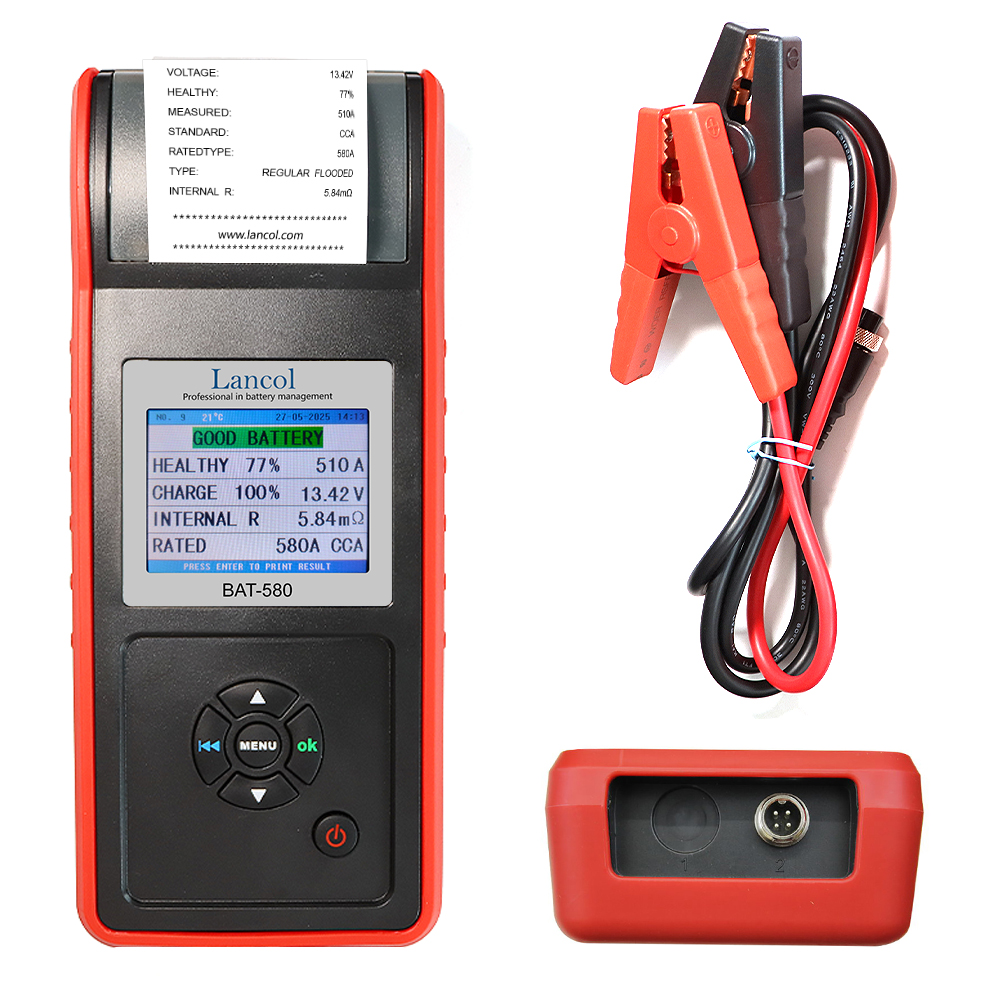
Kelvin clamp is an indispensable key accessory for battery testers, especially for internal resistance testing. It uses a unique four wire design to physically separate the current application channel and voltage measurement channel, eliminating the influence of test wire resistance and contact resistance on measurement results, thereby achieving high-precision measurement of battery internal resistance and terminal voltage. Without Kelvin clamps, the measurement of battery internal resistance will be severely distorted, losing its significance as a basis for judging battery health status. When selecting and using a battery tester, it is crucial to confirm that it is equipped with a genuine Kelvin clamp to obtain reliable data.
Our battery tester just use this kind of Kelvin clamp.